“Dimension Style”
We see now the part a bit more complicated, the command "Dimension style"
![]() .
.
On the ribbon, we find it here:
Through this command we will set the various characteristics of the dimensions, by clicking the command opens the following window "dimension style manager":
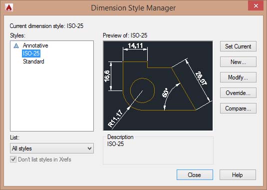
We see written in the upper left corner,the current dimension style is: "ISO-25".
In the central window is displayed a preview of the current dimension style, where we see the features set, color, font, arrows, etc.
Usually we will use one dimension style for each individual design, but we could use even more than one, with different characteristics from the first.
By using the “New…” and “Modify...” buttons , it will create a new style of dimension or modify the existing one, in this later case you should first select the current dimension style, in the left box, and then click the button “Modify…”.
For the moment, we opt for the second path, then select the style already current: ISO-25, which will be highlighted in blue in the image above and then click the “Modify...” button.
This will open the following window:
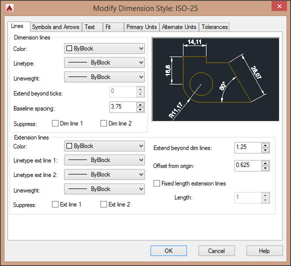
The "Modify Dimension Style" window is composed of seven tabs, through which you set the characteristics of dimension styles.
-
- Lines
-
- Symbols and Arrows
-
- Text
-
- Fit
-
- Primary Units
-
- Alternate Units
-
- Tolerances
We will examine the top five.
The table "Lines" , in the above image, relates to the lines that make up the dimensions.
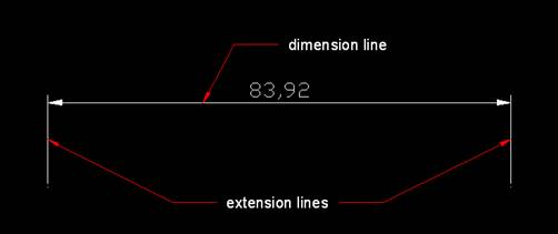
A dimension consists of the ‘Dimension lines’ and the ‘Extension lines’.
Through the first tab you are working on these lines, respectively, being able to choose the color, line type and thickness.
Through the “suppress” box, you can choose whether to make invisible the dimension line and one or both extension lines.
Generally, I change only the color of the lines to distinguish the dimension from the rest of the drawing.
In the boxes at the bottom right, we set the length of the extension line beyond the dimension line and the distance from the point of origin.
.

Alternatively, you can turn on a fixed measure for the extension lines and set it in the box below; in this way, the extension lines will all be the same length regardless of the distance that we put it from the object.
Set these values in a proportionate manner respect to dimensions and the rest of the design you're working on.
While we make these changes we will see update the dimension in the preview window; but on the actual dimensions in the drawing, will be apply at the time we will confirm with the OK button and close the “dimension style” window.
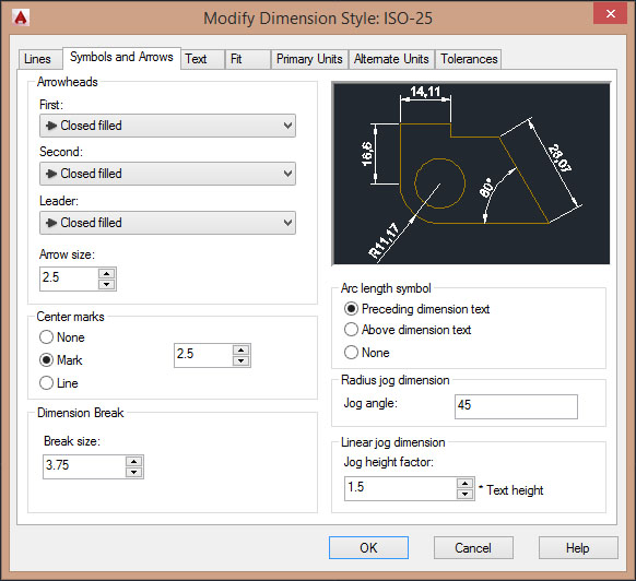
The second tab “Symbols and Arrows” operates mainly on the symbols at the end of the dimension line, for which we have several options to choose from.
Select the desired symbol from the dropdown list, you can normally use the “Closed filled” or “Architectural tick”.
On the third tab, “Text” set the text appearance of the dimension, then:
Text Style: (select a text style that you create for plain text (i.e. the Standard), so if necessary we can set two different characters for the text written on the drawing and that of dimensions)
Text Color: (set the color of dimension text)
Text Height: (set the height of the text. If we have already established a height in the “Text Style”, this will be apply to dimensions that using this style of text. Otherwise, we can set here the desired height for the text of the dimensions).
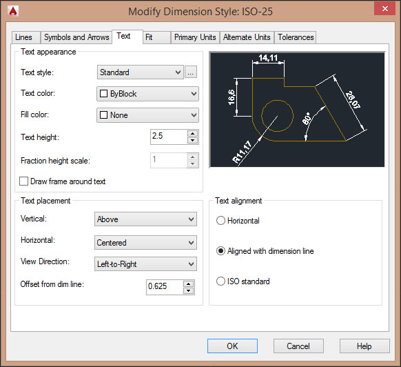
In the “Text placement”, set the position of text relative to the dimension line.
Set as image: vertical:Above and Horizontal: Centered
In this way, the text will stand vertically above the dimension line and horizontally centered on this.
In the “Offset from dim line” set the distance of text from the dimension line.
In the “Text alignment”, leave checked the “Aligned with dimension line”, so the text will be align with the dimension line.
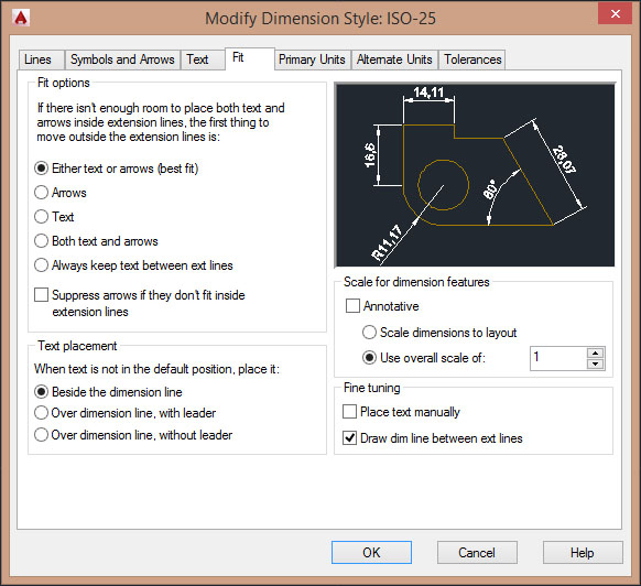
The fourth tab, "Fit", is used to determine how the dimension should behave when between extension line, if there isn't enough space to hold all the text and the arrows of dimension.
Leave everything set as we find, see the following image.
The fifth tab “Primary Units” is the most important:
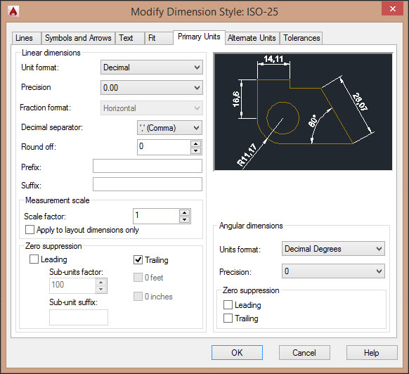
As we see in the image, action is taken separately on the "Linear dimensions" than on "Angular dimensions", left and right of the table.
In both cases, we have to set:
Unit format: (unit of measure used by dimension)
Set through the drop-down menu on "Decimal" and "Decimal Degrees" (decimal units).
Precision: (number of decimal places to display on the quote)
Select the number of decimal places according to the precision necessary for the dimension of what we are drawing.
E.g. if the design of masonry, may not be necessary to see the millimeters, while in other types of technical drawing can be important even tenths of a millimeter.
In general, however, may be fine set at “0.00”, to two decimal places.
For the linear dimensions also set the following values:
Round off: (Through “round off” can cause dimensions to measure with the approximation that we set in this field)
If we set the decimal values such as 0.5, dimensions shall be rounded to this value, so no matter how many decimal places we have to set the “Precision”, the dimensions neglect them and give us a “distorted” measure approximate to 0.5 decimal places.
If we put dimensions in “cm” with a “Round off” to 0.5, we will have dimension values with an accuracy of half a centimeter at a time.
If instead, we set the “Round off” to 0.1, will be more accurate in approximating one millimeter at a time.
If we consider the same dimensions in “mm”, in the first case we have (0.5) to an accuracy of half a millimeter and in the second case (0.1) to the tenth of a millimeter.
Measurement scale
Scale factor: (this is the scale factor applied to dimensions)
For example, setting this value to 0.1, the value of the dimensions will be equal to one tenth of the measured value.
As already mentioned in the introduction of dimensions, can be useful if in a drawing we use two different dimension styles, one for the basic design and one for the magnified details.
If we have a design within a particular magnified tenfold, the value of the dimension of this object will be ten times higher than the dimension of the basic model.
By using another dimension style with a “scale factor” set in this case 0.1, the details enlarged obtaining values equal to the basic model.
If necessary, we will use different colors for text or lines of two dimension styles to differentiate them.
Zero suppression:
The boxes “Leading” and “Trailing” placed under the heading “Zero suppression” serve, if selected, to remove the zero (if present), early (Leading) and at the end (Trailing), from dimension with decimals.
A dimension of 0.57 value will be show with .57 (Leading selected)
A dimension of 3.60 value will be show with 3.6 (Trailing selected)
We can set independently the “zero suppression” for linear dimensions and angles.
When dimension settings are done, click “OK” to close down the window and then the “Close” button in the dialog “Dimension style manager” to close this one.
Here, if dimensions are already on the drawing, should be automatically update, to reflect the new settings entered.
If we have dimension belonging to different dimension styles, will update only those belonging to the style changed.
Each new dimension to insert always belongs to the current dimension style.
With the command "dimension update"
![]() , find on the dimension toolbar, we can update any existing dimension in the current dimension style.
, find on the dimension toolbar, we can update any existing dimension in the current dimension style.
To create a new dimension style, reopen the "Dimension Style"
![]() manager
manager
On the "Dimension Style Manager" click on "New ..." button.
The following dialog:
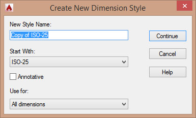
In this window, you can type up a name for your new dimension style “New Style Name:”
The new style will resume settings from one already exists, select the second menu “Start with:”
On the last drop down “Use for”, leave “All dimensions”.
Click on “Continue” and will enter the window where we will change the style settings, as we have seen before.
When finished, click OK and the new parameter style is created and appears with the chosen name in the list with the others present.
Now all that remains is to make it “current” by clicking on “Set Current” and close the window, to use it.
Tweet