Part 7
Finally we reached the time to print our work, we should have at least a small printer installed on the computer with which we can print on A4 or A3 formats, but if we need a larger format printing, such as an A0 or even more, we need a plotter.
These output devices can be installed either locally on your PC, or on the network, as usually happens in companies.
In practice AutoCAD can use any printer that is installed and running on our operating system.
“Plot”
The“Plot” command
![]() is on the "Standard Toolbar":
is on the "Standard Toolbar":

Alternatively, we can open the menu by clicking the red symbol of AutoCAD, upper left on screen and then select “Print”.
We can click on the classic “File” menu and select “Plot”, or we can simply use the appropriate keyActivating the command, it will open the following dialog:
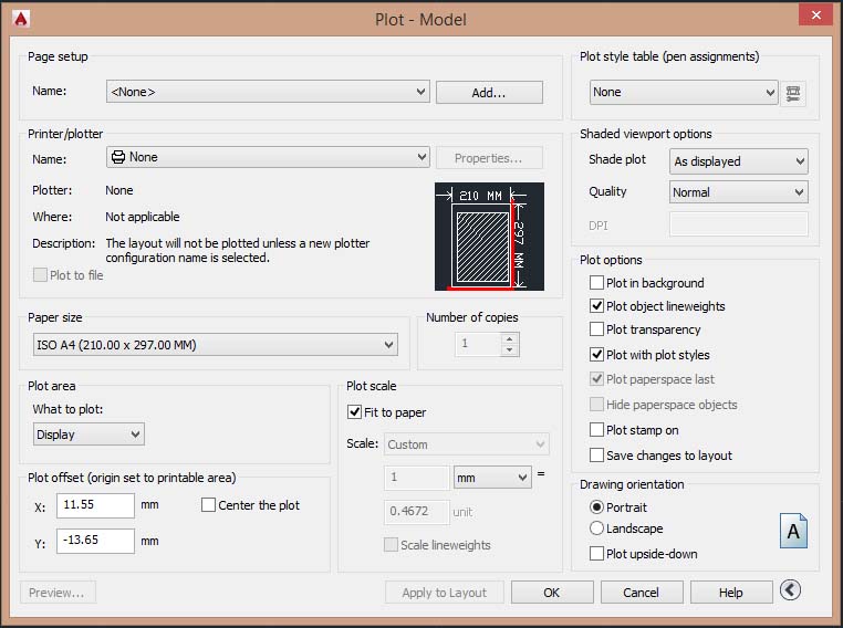
From here, we will manage all the settings needed to print and then send the design to the printer or plotter.
As we have seen in other cases, the print window is divided into several sections indicated by their titles, let's see:
Printer/plotter
Here we can open the drop-down menu and will select the printer to use, among those installed on our operating system or network.
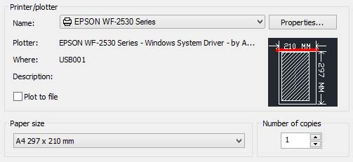
In the section “Paper size”, select the desired format, including those that the printer offers: A4, A3, A2, etc...
On the “Number of copies”, set the number of copies to print.
In the small window with black background, is represented the paper where we are going to print, with its size.
Within this schematic paper is included the area that we are going to print, which, also according to the scale will be assigned, it is bordered red if not contained in the selected paper size.
“Plot area”: Here we choose the part of our drawing that we want to print.
On the drop-down menu, select “window” between the available items.
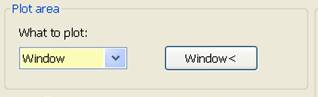
Just did it, we must select on screen the part of the design that we intend to print.
We will then click twice on the screen to define a rectangular window that delimit what we want to print.
We can then select an area slightly outside the entire drawing or a part of this.
Just set the print area redisplay the Plot window, if necessary, by clicking again on the "window" button, we will immediately redefine the area to print.
"Plot offset:"
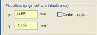
In these boxes we can determine how much ‘mm’ we want to move the drawing from the edge of the paper where we are going to print, in the horizontal and vertical (X and Y).
In fact, any printer can not cover all the selected paper size but leave the blank margin around it.
For each selected paper size, we will have an effective area of the print that will be slightly smaller than the paper chosen.
The values of “Plot offset”, will therefore refer to the edge of the effective print area.
If you check the box “Center the plot”, the printed design will be centered in the actual printing area of the paper chosen.
“Plot scale”:
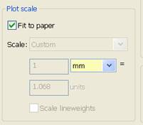
In the “Plot scale” area, will set the scale factor for our design.
If you check “Fit to paper”, the design will be print at the maximum dimension allowed by the selected paper size, occupying the entire print area available.
Leaving this box empty instead, we can go and set in the other sections, the scale value that we want.
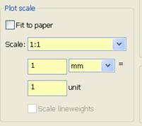
In this first drop-down menu you can
select a scale value of the many options available:
1:1 - 1:2 - 1:10 to 1:20
- 2:1 - 10:1 etc..
We also have values in inches, if we need.
Once setting the scale with drop-down menu, we see the same values are reported in the two boxes below. If necessary is possible to manually enter the desired value in these two boxes, even if different from the default values in the drop down, their purpose would be just that.
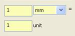
Important is to set in the other smaller menu, the millimeters “mm” or “inches”.
We read so that 1 mm printed is equal to 1 unit on the drawing in AutoCAD.
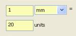
Or that 1 mm print is 20 units of the drawing in Autocad.
The 1:1 value correspond to the "full scale", in fact one Autocad unit will correspond to one millimeter on the printed paper.
Now comes the part a little more complicated, we must bear in mind how "we" have decided to interpret the units of Autocad when we did the drawing, if in millimeters or centimeters.
For example, if we drew a square of 100x100 mm units considering, if you print it in 1:1 scale, on paper will be a square of 100x100 mm.
The same picture could be the plan of a table 100 cm x 100 cm
In this case we consider a unit equal to one centimeter of autocad.
Like before printing it on a 1:1 scale, will get the same square of 100x100 mm, or 10x10 cm if you want...
This measure therefore corresponds to one tenth of the table so that in reality would be 1 meter x 1 meter ... so we did a drawing on paper that is in 1:10 scale compared to the real object we want to represent.
So, considering the drawing units in millimeters, a print scale of 1:1 correspond to "true".
1:2 will be 1:2 and 1:10 will be 1:10, 1:20 will be 1:20 etc. Let's say you consider the units as mm would be the standard to be adopted.
But as we have seen is not always so because if we draw a room is easier to define the size in centimeters than in mm.
Considering therefore the units as centimeters, a print set at 1:1 scale, on paper correspond to 1:10.
1:2 will be 1:20, 1:5 will be 1:50, but if we want to print the "full scale" will set 10:1.
This will be quite obvious if you happen to need to print a drawing done by others, in that case, our first concern will be to understand the terms of units that were considered by the designer.
Normally we are aware of the type of object that has been designed and we are working on, that if a plan of a house, furniture, mechanical, etc..
From here we will be able to evaluate, by measuring with the command "distance", an object on the design of which we know the "nature" and the proportions, then comparing the resulting size on Autocad with its extent in reality.
.
Here's an example: I open the drawing of a house plant that I have to print, its units may have been considered by the designer in millimeters, centimeters or even meters.
To understand, measure the "distance" to an object which may know the proportions, the thickness of a wall, or the width of a door.
If the thickness of a wall will result 200 units, obviously design is considered in "mm" as the thickness of a wall can be 20 cm in reality.
If the measure will give me 20, the design has been interpreted in cm.
If the same size will give me 0.2 means that the units have been interpreted in meters.
When printing a drawing interpreted in meters with a scale of 1:1 will be printed in 1:100 scale.
We should therefore pay attention to these evaluations, alternately, in some cases it is useful to scale the entire drawing with the "scale"command, to resize it in more "friendly" units, then scaling the design of which I spoke to 100, the wall thickness of 0.2 will result 20.
I then scaled the units to centimeters, which to me are easier to interpret and to draw upon it to set the scale for printing.
It will also be important to remember to write on the drawing, the scale factor that represents the design on paper (which as we have seen is not necessarily the same as the one set to print) so that it becomes clear to any employee who will view the drawing paper, the proportions of this than the reality.
Depending on the scale set to print so the picture will have different dimension on paper and then we need to use different sizes of paper, based on this.
We will probably have to create a mask with the design also will report on which any company logo, title of the drawing, description, scale etc..
The size of the printed mask, which normally correspond to a sheet of A4 paper ( 210x297 mm on the basis of which the design can be folded ), will always remain the same regardless of the scale factor used.
So we must scale the template to fit the scaling factor used to print.
Then
:
210x297 is 1:1 scale
We will scale double for 1:2 print, then it will be 420x594 on Autocad
We will scale for 10 times to 1:10 print, then it will be 2100x2970 units on Autocad.
From the measurement of the mask (if we know that these proportions are used) we can also understand what scale factor should be use to print a drawing made by others.
Well, when we come to the correct scale factor we could press the OK button to send your drawing to the printer that will do the rest of the work...
But let's move on...
Tweet